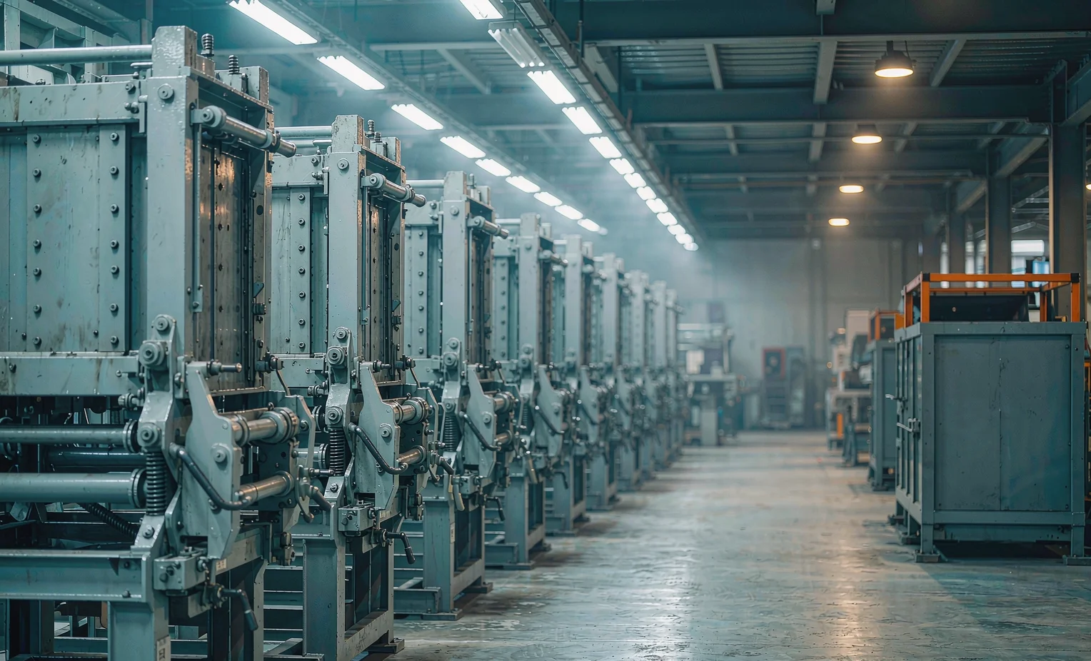
A battery plant layout is usually drawn around the building: where the columns are, where the loading bay is, where the power comes in. That is the wrong starting point. The layout should be drawn around the process, and then reconciled with the building.
The forward-only principle
Material should move forward through the plant and never back. Every backward move — plates returning to a machine they already passed, paste going back to the mixer, cured plates going back for a touch-up — adds handling, damage risk and a place for errors to hide.
When a layout forces backward flow, the cause is almost always one of three things: a station with insufficient buffer, a station with lower capacity than its neighbours, or a quality check placed after the point where the defect can still be fixed cheaply.
The sequence
- Raw material store — lead, oxide, acid, separators, containers. Keep acid separated and bunded.
- Grid casting or expanded metal — the first hot process, needs ventilation and its own extraction.
- Paste mixing — close to pasting, because paste has a short working life.
- Pasting and flash drying — the highest scrap-risk step; put inspection right after it.
- Curing — a large, environmentally controlled block. This is the anchor of the layout.
- Assembly — brushing, enveloping, grouping, welding, containerisation.
- Formation and charging — high current, high heat, needs its own ventilation and cooling.
- Wash, dry, test, pack — the last chance to catch a defect before it ships.
Put curing and formation as far apart as the building allows. Both are heat-and-fume processes, and putting them together concentrates the problem.
Buffers, not storage
Between each pair of stations there should be a deliberate buffer sized to the changeover time of the downstream station, not to a week of production. Large buffers hide problems: a machine can be down for two days before anyone notices, because the buffer absorbed it.
Size the buffer so that a stoppage becomes visible within one shift. That is uncomfortable and it is correct.
Where the area actually goes
| Area | Share of floor | Notes |
|---|---|---|
| Curing and drying | 25–35% | Rack density drives this, not machine footprint |
| Formation and charging | 15–25% | Water, acid and cooling all compete for space |
| Assembly | 15–20% | Conveyorised or cellular, depending on volume |
| Pasting and mixing | 10–15% | Paste return routing needs thought |
| Stores, utilities, aisles | 20–25% | Usually under-provided |
Design for the second line
Almost every plant we have equipped has added capacity within five years. Leave the corridor width, the utility headers and the extraction capacity for the second line at the drawing stage. Retrofitting them into a running plant costs several times what it costs to allow for them now.